- Familiar with Microchip Curiosity Development Board
- Install and setup MPLAB X IDE
- Familiar with DAC, CLC, TMR, PWM and C programming, and basic MPLAB IDE operation.
- Confirm multiple independent function can be executed in PIC16F1619.
Project Initial Setup:
- Hardware:
- One "Curiosity Development Board", from Amazon, $20.
- One mini USB cable
- One Oscilloscope
- Software:
- Install MPLAB X IDE from https://microchipdeveloper.com/mplabx:installation
- Resource: https://www.youtube.com/watch?v=7MqyU0Lxj08
Start A New MPLAB Program (draft note only):
- Start MPLAB
- File--> Stand along project
- Enter device name, in my case, it is PIC16F1619
- Select "None" for debug header
- Select "Curiosity" in select tool window
- Select "XCB" in select compiler window. Install one if missing.
- Provide project name, such as "My test code"
- Save "MyConfig.mc3" in "Save MCC Configuration File" window.
- Choose "PDIP20" in package pull down tab in "Pin Management Grid View".
- MPLAB is ready for programming
Project Objective:
- Setup "Saw Shape" signal generator with C code and DAC peripheral.
- General two clocks, they are 250KHz and 500Hz with TMR and PWM peripheral. Setup up one switch to select signal with CLC peripheral but without using CPU's resource.
- About two signals process are run simultaneously and independently.
System Environment Setup:
 |
| Required Peripherals List |
 |
| Setup Oscillator with "INTOSC..." and "1MHz". This internal clock setting affect saw signal frequency directly. |
 |
| Pin module setting -1 |
 |
| Pin module setting -2 |
Saw Shape Signal Generator:
 |
| Add a simple DAC code |
 |
| Make sure check two check boxes. |
 |
| DAC1OUT>>RA0, see the lock symbol in green box. |
For 250K and 500 Hz Signal Switch:
 |
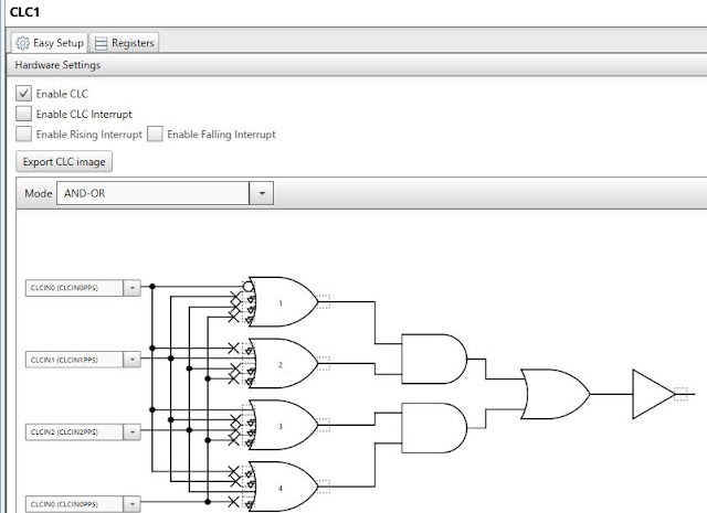
| CLC1 setting, need assign "CLCIN0" and "CLCIN1" in above chart. S1 >> RC4 >>CLCIN0 choose signal between CLCIN1 << PWM3 or CLCIN2<<PWM4 |
 |
| PWM3OUT>>CLCIN1, please note the right two corners' link symbol at RC3 (not show). |
 |
| PWM4OUT>>CLCIN2, , please note the right two corners' link symbol at RC2 (not show). |
 |
| CLC1OUT>>RC5, see lock symbol in green box. |
 |
| Signal Flowchart, use RC4 to control switch to provide either 500Hz or 250KHz output to RC5. |
 |
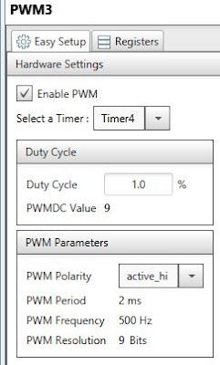
| Set clock range and precise Timer Period. The Timer Period (ex, 2ms) define the timer frequency. |
 |
| Set duty cycle and source of timer. |
 |
| Set timer |
Testing Microchip:
 |
| Ground: blue wire, RA0: white wire DAC output, RC5, blue wire timer/PWM signal output. |
 |
| Yellow line: 230Hz saw signal has been generated by DAC and C code. Its signal is not linear and very noise. It could be a DAC bug from PIC16F1619. |
 |
| Blue line: 250K Hz clock when S1 is off/not pressed. Yellow line from generated by DAC which is quite noise. |
 |
| S1 switch |
 |
| Frequency has been dropped to 500Hz clock when S1 is pressed. |
Programming Code:
#include "mcc_generated_files/mcc.h"
void main(void)
{
// initialize the device
SYSTEM_Initialize();
uint8_t count=0;
DAC1_Initialize();
while (1)
{
for(count=0; count<=255; count++)
{
DAC1_SetOutput(count);
//__delay_ms(1);
}
}
}
Summary:
This 20$ Curiosity Development Board is a very a very different but a powerful board compare to Arduino. You can set and execute multiple functions on the same chip and run interdependently. Many functions can be operated without using CPU resource too.
My favor peripheral are Timer, PWM and CLC. They can be set easy without code, and run very fast. My less favor part is DAC because it is very slow and very noise at the same time. The worst part is poor signal linearity issue.
I am happy having this board, and will use it on my future project. However, the first time I try it, I almost give up and return it back to Amazon within the same day. Here is why:
- Cannot find much information on book or internet about this board.
- MPLAB X IDE is very complicate.
- Many operation concept are new compare to Arduino's.
- It is for advance user. Very steep learning curve.
- Cannot follow some examples since it demos with a different board from Microchip website. Some peripheral's name, and option are different in their demonstration.
- User much familiar with C programming coding.
- User must familiar with logical gate.
- User must has sufficiency tool to work with this board, such as oscilloscope and etc.
- Microchip company do not provide example or detail description on many peripheral such as AT, CCP, CRC, CWG, ZDC, MSSP, FVR and etc.
PIC16F1619 is a power chip, it opens a new application opportunity to me such as HDMI signal handling, and different clock signal source. But NOT recommend for beginner unless you can find help from experienced user.
This is my first time using this board. When writing this blog, I only have about two days trial and error experience on this board. If you see error, please do not hesitate let me know. Thanks.
Resource:
Helpful resource: https://microchipdeveloper.com/. PWM: https://www.youtube.com/watch?v=7MqyU0Lxj08

No comments:
Post a Comment