ATtiny85-101 Initial Setup
with correct pre-installed bootloader
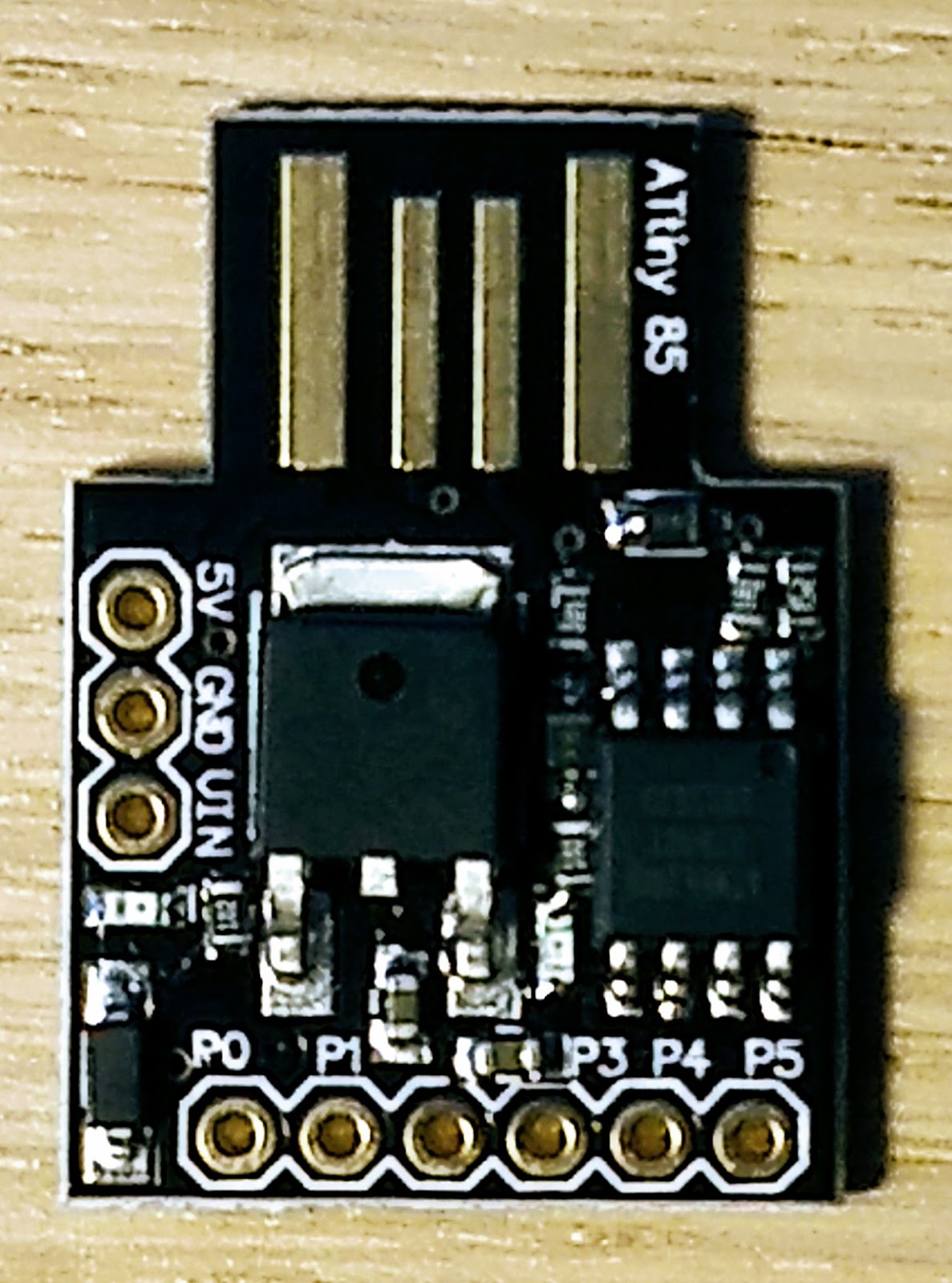
with correct pre-installed bootloader
Note: This procedure only work for some ATtiny85 board with proper pre-installed bootloader that can work with USB directly.
Many boards from the market may not have correct version bootloader installed. I use below link as my reference, but it does not work with the #1 board, I purchased from Amazon. https://www.electromaker.io/blog/article/introduction-to-the-attiny85-19. If so, see the note section for its solution. Good luck!
#2: https://www.amazon.com/gp/product/B07KVS4YGQ/ref=ppx_yo_dt_b_asin_title_o03_s00?ie=UTF8&psc=1 (it is with correct version pre-installed bootloader, that can work with USB cable directly.)
Setup Procedure:
Step 1: Open the Arduino application and click on File >> Preferences and past the following into the Additional Boards Managers URLs: dialog.
http://digistump.com/package_digistump_index.json
Step 2: Go to Tools >> Board >> Boards Manager and from the drop-down menu select “Contributed”. and choose Select the “Digistump AVR Boards” and click Install.
In case it fails, try to install it manuelly with: C:\Users\**YOUR USERNAME**\AppData\Local\Arduino15\packages\digistump\tools\micronucleus\2.0a4\post_install.bat
Step 3: Go to Tools >> Board >> and select Digispark (Default - 16.5MHz) don’t worry about the Port.
Step 4: Copy and paste below program to Arduino IDE and save it.
Step 5: Make sure the ATtiny85 is unplugged from USB.
Step 6: Upload below code to ATtiny85. Wait for below instruction to plug the ATtiny85 to USB cable.
Step 7: After the upload is completed, IDE will show below message. P3 and P4 LED will blinking while code is uploading.

Step 8: The upload is completed, and your ATtiny85 should running without problem.
Note:
10/25/2019 update: There is a problem with my ATtiny85. As soon as I unplug it from USB, it FORGET its code.
10/29/2019 update: After burn a proper bootloader to the board, the above problem has been resolved. See this link for solution.
Seeking for solution:
1. Such as program the ATtiny85 only, such as https://www.instructables.com/id/Programming-ATtinys-Micro-Controllers-With-Arduino/
2. Use the one with micro USB attached to its board such as https://www.amazon.com/gp/product/B07KVS4YGQ/ref=ppx_yo_dt_b_asin_title_o01_s00?ie=UTF8&psc=1
ATtiny85 Code in Arduino IDE
void setup() {
pinMode(0, OUTPUT);
pinMode(1, OUTPUT);
pinMode(2, OUTPUT);
pinMode(3, OUTPUT);
pinMode(4, OUTPUT);
}
void loop() {
digitalWrite(0, HIGH);delay(200);
digitalWrite(1, HIGH);delay(400);
digitalWrite(2, HIGH);delay(600);
digitalWrite(3, HIGH);delay(800);
digitalWrite(4, HIGH);delay(1000);
digitalWrite(4, LOW);delay(20);
digitalWrite(3, LOW);delay(20);
digitalWrite(2, LOW);delay(20);
digitalWrite(1, LOW);delay(20);
digitalWrite(0, LOW);delay(300);
}
Schematic:
 |
| Source: https://s3.amazonaws.com/digistump-resources/files/97a1bb28_DigisparkSchematic.pdf |
ATtiny85 Datasheet
- 8 pins
- 8KB ISP flash memory
- 512-Byte EEPROM
- 512-Byte SRAM
- 6 general purpose I/O lines
- 32 general purpose working registers
- One 8-bit timer/counter with compare modes
- One 8-bit high speed timer/counter
- USI
- Internal and external Interrupts
- 4-channel 10-bit A/D converter
- Programmable watchdog timer with internal oscillator
- Three software selectable power saving modes
- DebugWIRE for on-chip debugging.
- The device achieves a throughput of 20 MIPS at 20 MHz and operates between 2.7-5.5 volts


