Sunday, March 8, 2020

Weather station with ESP8266, DHT22 and BMP280

Objective:
  Setup a weather station with ESP8266 ESP-01, DHT22 and BMP280.  It also come with remote switch.

Note: 
  The experience from this project can be transfer to another project quickly.  Such as application with I2C and ESP8266.  The MQTT setup is not part of the scope of this project demonstration; therefore, it is not discussed here.

Learned lesson: 
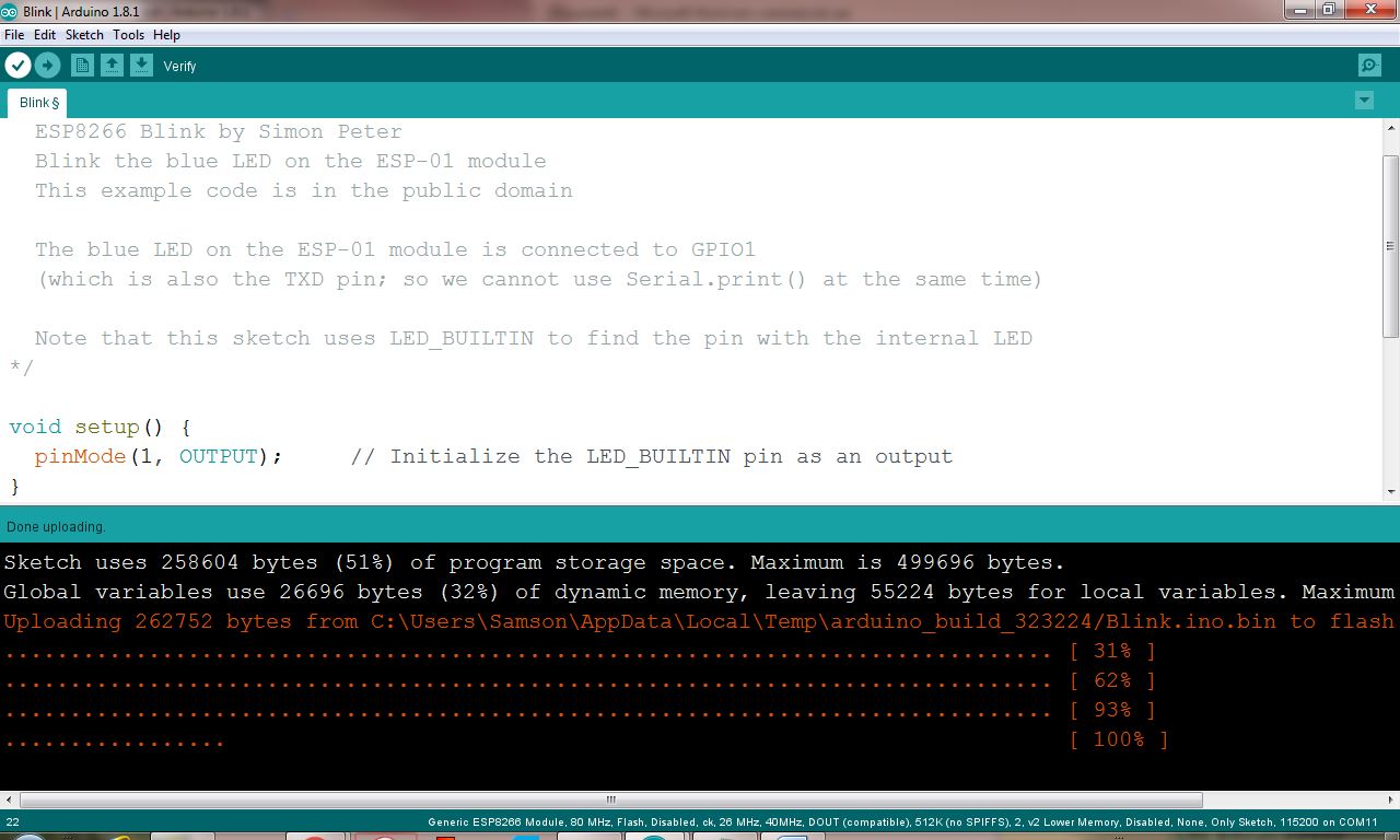
1. How to program ESP8266 ESP-01.  See my other post at https://ap170210.blogspot.com/2020/03/program-esp8266-01-with-usb-to-esp8266.html
2. CH_PD/EN has to connect to 3.3V in order to work properly.
3. I2C set up with ESP8266 is different from Arduino.  For example, I must add Wire.pins(0, 2); Wire.begin(0, 2);   in order to make I2C work.  But Arduino Uno does not need it.
4. The location of SCL and SDA on ESP8266.
5. When program GPIO0 (not in this example) since it is grounded during the programming, do NOT set it to HIGH, it will damage your chip.


Code:
//Reference website
//https://lastminuteengineers.com/bmp280-esp8266-weather-station/
//https://www.theengineeringprojects.com/2019/05/introduction-to-esp-01.html
//https://www.instructables.com/id/One-More-Arduino-Weather-Station-ESP-01-BMP280-DHT/
//In order function properly, CH_PD/EN must connect to 3.3V

//BMP280 SDA -- ESP-01 GPIO0
//BMP280 SCL -- ESP-01 GPIO2
//BMP280 VCC -- 3.3V
//BMP280 GND -- GND
//DHT22 signal -- Tx(GPIO1)
//DHT22 VCC -- 3.3V
//DHT22 GND -- GND
//ESP-01 CH_PD/EN -- 3.3V

#include <ESP8266WiFi.h>
#include "Adafruit_MQTT.h"
#include "Adafruit_MQTT_Client.h"

#include <Wire.h>
#include <Adafruit_Sensor.h>
#include <Adafruit_BMP280.h>
#include "DHT.h"

/************************* WiFi Access Point *********************************/
#define WLAN_SSID       "**********"
#define WLAN_PASS      "**********"
/************************* Adafruit.io Setup *********************************/
#define AIO_SERVER      "io.adafruit.com"
#define AIO_SERVERPORT  1883                   // use 8883 for SSL
#define AIO_USERNAME    "**********"
#define AIO_KEY         "**********"

// DHT Sensor
#define DHTTYPE DHT22
uint8_t DHTPin = 1;  
DHT dht(DHTPin, DHTTYPE); 
float temperature_dht, humidity_dht;  

//Initialize BMP sensor              
Adafruit_BMP280 bmp;
float temperature, pressure, altitude;

// Create an ESP8266 WiFiClient class to connect to the MQTT server.
WiFiClient client;

// Setup the MQTT client class by passing in the WiFi client and MQTT server and login details.
Adafruit_MQTT_Client mqtt(&client, AIO_SERVER, AIO_SERVERPORT, AIO_USERNAME, AIO_KEY);

/****************************** Feeds ***************************************/
Adafruit_MQTT_Publish bmp_temp =      Adafruit_MQTT_Publish(&mqtt, AIO_USERNAME "/feeds/bmp_temp");
Adafruit_MQTT_Publish bmp_pressure =  Adafruit_MQTT_Publish(&mqtt, AIO_USERNAME "/feeds/bmp_pressure");
Adafruit_MQTT_Publish dht_humidity =  Adafruit_MQTT_Publish(&mqtt, AIO_USERNAME "/feeds/dht_humidity");
Adafruit_MQTT_Publish dht_temperature =  Adafruit_MQTT_Publish(&mqtt, AIO_USERNAME "/feeds/dht_temperature");
Adafruit_MQTT_Subscribe onoffbutton = Adafruit_MQTT_Subscribe(&mqtt, AIO_USERNAME "/feeds/onoff");

int onoffpin=1;
/*************************** Sketch Code ************************************/
void MQTT_connect();

void setup() {
  //I2C stuff, without it, ESP8266 ESP-01 cannot work properly
  Wire.pins(0, 2); Wire.begin(0, 2);    
  bmp.begin(0x76); delay(100);

  pinMode(DHTPin, INPUT);
  dht.begin(); delay(100);
  
  WiFi.begin(WLAN_SSID, WLAN_PASS); while (WiFi.status() != WL_CONNECTED) {delay(500);}
  pinMode(onoffpin, OUTPUT); mqtt.subscribe(&onoffbutton);
}

void loop() {
  MQTT_connect();
  Adafruit_MQTT_Subscribe *subscription;
  while ((subscription = mqtt.readSubscription(5000))) {
    if (subscription == &onoffbutton) {
      if(onoffbutton.lastread[1]==78){digitalWrite(onoffpin,LOW);}
      if(onoffbutton.lastread[1]==70){digitalWrite(onoffpin,HIGH);}
    }
  }
  temperature = bmp.readTemperature()-2.1;  //2.1 is the calibration factor
  pressure = bmp.readPressure() / 100.0F;
  //altitude = bmp.readAltitude(1015);  //1015 is the pressure at ~San Jose sea level
  temperature_dht =dht.readTemperature()-0.9; //0.9 is a calibration factor
  humidity_dht=dht.readHumidity();
  
  // Now we can publish stuff!
  if (pressure>0){
    bmp_temp.publish(temperature);delay(2000);
    bmp_pressure.publish(pressure);delay(2000);
  }
  if (humidity_dht>0){
    dht_temperature.publish(temperature_dht);delay(2000);
    dht_humidity.publish(humidity_dht);delay(2000);
  }
}

// Function to connect and reconnect as necessary to the MQTT server.
// Should be called in the loop function and it will take care if connecting.
void MQTT_connect() {
  int8_t ret;
  // Stop if already connected.
  if (mqtt.connected()) {return;}
  uint8_t retries = 3;
  while ((ret = mqtt.connect()) != 0) { // connect will return 0 for connected
       mqtt.disconnect(); delay(5000);  // wait 5 seconds
       retries--;
       if (retries == 0) {while (1);} // basically die and wait for WDT to reset me   
  }  
}


BMP280 I2C Code


Objective: 

  • Demo a temperature and pressure reading from BMP280 with Arduino.


Connection:
        Arduino -- BMP280
5V (or 3.3V) -- Vcc
            GND -- GND
                A5 -- SCL
                A4 -- SDA

Note: 
    BMP280 work with 5V and 3.3V.  This BMP come with Vcc, GND, SCL, SDA, CSB and SDD.  Only the first four been connected in this project.


Arduino Code:
#include <Adafruit_BMP280.h>   // include Adafruit library for BMP280 sensor
Adafruit_BMP280 bmp; // I2C

void setup() {
  Serial.begin(115200); delay(100);
  bmp.begin(0x76); delay(100);
}

void loop() {
  Serial.println(bmp.readTemperature());delay(100);
  Serial.println(bmp.readPressure());delay(100);
  Serial.println(bmp.readAltitude(1013.25));delay(100);  //SEALEVELPRESSURE_HPA = 1013.25
}

Saturday, March 7, 2020

Program ESP8266-01 with USB to ESP8266 Adapter for Arduino


Objective: 
  • Demonstrate how to program ESP8266 ESP-01 with its USB adapter

Equipment: 
  • ESP8266 ESP-01
  • ESP8266 USB adapter
  • Shorting wire/assembly
ESP8266 kit can be purchased from Amazon.com

Learned Lesson:
1. GPIO0 has be grounded in order to program it.
2. CH_PD/EN need to connected to 3.3V in order to use ESP-01 after program is completed.
3. Software version must use 2.5.0.  Other version may not work.


Program Procedure:
  • Open Arduino IDE
  • In File --> References, enter "http://arduino.esp8266.com/stable/package_esp8266com_index.json" in "Additional Board Manager URLs" text box.

  • In Tool --> Board: --> Board Manager type in 8266
  • Install version 2.5.0.  Note: the correct version is very important.  
  • In Tool --> Board: select "Generic ESP8266 Module"

  • Modify "USB to ESP8266 Adapter for Arduino" module for shorting GND and GPIO0 temporary.


  • Connect ESP8266-01 to above module and insert to computer's USB port


  • Choose correct port.  From Tool --> Board: select correct port, in below example, it is COM 7.

  • Open test file.  From File --> Examples --> ESP8266 --> Blink
  • Upload the Blink program
  • After upload is complete, the ESP8266-01's led should be blinking now.  

  • If you want to program the same module again, please power cycle it (unplug and plug in from the USB port) before program it.

Trouble shooting:
  1. Check your wiring
  2. Check your ESP8266's driver version is 2.5.0
  3. GND and GPIO0 has been shorted.
  4. Power cycle it

Proclamation: 
Bonus:
Program ESP8266 ESP-01 with FT232RL FTDI USB to TTL Serial Converter Adapter


Proclamation: 
  Below procedure is inspired from https://iot-playground.com/blog/2-uncategorised/67-arduino-esp8266-ide


Procedure:
1. Plug in above USB adapter
2. Check if your computer can find its COM port if yes, skip to step 4
3. Install driver manually from https://www.ftdichip.com/Drivers/VCP.htm or just run the EXE file from https://www.ftdichip.com/Drivers/CDM/CDM21228_Setup.zip.
4. Connect your adapter as shown in below diagram.
5. Setup your Arduino IDE for ESP8266 as shown in previous procedure.
6. Upload a test program, it should work now.
7. Before your try to upload another program, you need to reset it first (unplug and plug its power pin).
 https://iot-playground.com/blog/2-uncategorised/67-arduino-esp8266-ide


Other Code Example:
  Below code is using ESP8266 ESP-01 with Adafruit's MQTT.  LED on ESP-01 can be remotely turned on or off, and ESP-01 push a new value to io.adafruit.  It is just for your reference only, and we will not discuss it in this project.

#include <ESP8266WiFi.h>
#include "Adafruit_MQTT.h"
#include "Adafruit_MQTT_Client.h"

/************************* WiFi Access Point *********************************/

#define WLAN_SSID       "*******"
#define WLAN_PASS       "*******"

/************************* Adafruit.io Setup *********************************/

#define AIO_SERVER      "io.adafruit.com"
#define AIO_SERVERPORT  1883                   // use 8883 for SSL
#define AIO_USERNAME    "*******"
#define AIO_KEY         "*******"


WiFiClient client;
Adafruit_MQTT_Client mqtt(&client, AIO_SERVER, AIO_SERVERPORT, AIO_USERNAME, AIO_KEY);

Adafruit_MQTT_Publish   count =  Adafruit_MQTT_Publish(&mqtt, AIO_USERNAME "/feeds/count");
Adafruit_MQTT_Subscribe onoffbutton  = Adafruit_MQTT_Subscribe(&mqtt, AIO_USERNAME "/feeds/onoff");

void MQTT_connect();

void setup() {
  Serial.begin(115200); delay(10);

  // Connect to WiFi access point.
  Serial.println(); Serial.println();
  Serial.print("Connecting to ");
  Serial.println(WLAN_SSID);

  WiFi.begin(WLAN_SSID, WLAN_PASS);
  while (WiFi.status() != WL_CONNECTED) {
    delay(500);
    Serial.print(".");
  }
  Serial.println();

  pinMode(1, OUTPUT);
  
  Serial.println("WiFi connected");
  Serial.println("IP address: "); Serial.println(WiFi.localIP());

  // Setup MQTT subscription for onoff feed.
  mqtt.subscribe(&onoffbutton);
}

int count_value=0;

void loop() {
  MQTT_connect();
  Adafruit_MQTT_Subscribe *subscription;
  while ((subscription = mqtt.readSubscription(5000))) {
    if (subscription == &onoffbutton) {
      Serial.print(F("Got: "));
      Serial.println((char *)onoffbutton.lastread);
      if(onoffbutton.lastread[1]==78){digitalWrite(1,HIGH);Serial.print("Light on");}
      if(onoffbutton.lastread[1]==70){digitalWrite(1,LOW);Serial.print("Light off");}
    }
  }
  
  count_value++ ;
  
  // Now we can publish stuff!
  Serial.print(F("\nSending pressure val ")); Serial.print(count_value);Serial.print("...");
  if (! count.publish(count_value)) {Serial.println(F("Failed"));} else { Serial.println(F("OK!"));  }
  delay(1000);

}

// Function to connect and reconnect as necessary to the MQTT server.
// Should be called in the loop function and it will take care if connecting.
void MQTT_connect() {
  int8_t ret;

  // Stop if already connected.
  if (mqtt.connected()) {
    return;
  }

  Serial.print("Connecting to MQTT... ");

  uint8_t retries = 3;
  while ((ret = mqtt.connect()) != 0) { // connect will return 0 for connected
       Serial.println(mqtt.connectErrorString(ret));
       Serial.println("Retrying MQTT connection in 5 seconds...");
       mqtt.disconnect();
       delay(5000);  // wait 5 seconds
       retries--;
       if (retries == 0) {
         // basically die and wait for WDT to reset me
         while (1);
       }
  }
  Serial.println("MQTT Connected!");
}


Tuesday, October 29, 2019

ATtiny85-101 Initial Setup (with correct pre-installed bootloader)

ATtiny85-101 Initial Setup 
with correct pre-installed bootloader

Note: This procedure only work for some ATtiny85 board with proper pre-installed bootloader that can work with USB directly. 

Many boards from the market may not have correct version bootloader installed.  I use below link as my reference, but it does not work with the #1 board, I purchased from Amazon.  https://www.electromaker.io/blog/article/introduction-to-the-attiny85-19.  If so, see the note section for its solution.  Good luck!

Part: #1: https://www.amazon.com/gp/product/B07FCHFB85/ref=ppx_yo_dt_b_asin_title_o02_s00?ie=UTF8&psc=1 (it is with wrong version pre-installed bootloader.  It cannot work with USB connect directly.)

#2: https://www.amazon.com/gp/product/B07KVS4YGQ/ref=ppx_yo_dt_b_asin_title_o03_s00?ie=UTF8&psc=1 (it is with correct version pre-installed bootloader, that can work with USB cable directly.)

Setup Procedure:
Step 1: Open the Arduino application and click on File >> Preferences and past the following into the Additional Boards Managers URLs: dialog.
http://digistump.com/package_digistump_index.json 

Step 2: Go to Tools >> Board >> Boards Manager and from the drop-down menu select “Contributed”. and choose Select the “Digistump AVR Boards” and click Install.
In case it fails, try to install it manuelly with: C:\Users\**YOUR USERNAME**\AppData\Local\Arduino15\packages\digistump\tools\micronucleus\2.0a4\post_install.bat

Step 3: Go to Tools >> Board >> and select Digispark (Default - 16.5MHz) don’t worry about the Port.

Step 4: Copy and paste below program to Arduino IDE and save it.

Step 5: Make sure the ATtiny85 is unplugged from USB.

Step 6: Upload below code to ATtiny85.  Wait for below instruction to plug the ATtiny85 to USB cable.


Step 7: After the upload is completed, IDE will show below message.  P3 and P4 LED will blinking while code is uploading.


Step 8: The upload is completed, and your ATtiny85 should running without problem.

Note:
10/25/2019 update: There is a problem with my ATtiny85.  As soon as I unplug it from USB, it FORGET its code.
10/29/2019 update: After burn a proper bootloader to the board, the above problem has been resolved.  See this link for solution.


Seeking for solution:
1. Such as program the ATtiny85 only, such as https://www.instructables.com/id/Programming-ATtinys-Micro-Controllers-With-Arduino/

2. Use the one with micro USB attached to its board such as https://www.amazon.com/gp/product/B07KVS4YGQ/ref=ppx_yo_dt_b_asin_title_o01_s00?ie=UTF8&psc=1

ATtiny85 Code in Arduino IDE
void setup() {
  pinMode(0, OUTPUT);
  pinMode(1, OUTPUT);
  pinMode(2, OUTPUT);
  pinMode(3, OUTPUT);
  pinMode(4, OUTPUT);
}

void loop() {
  digitalWrite(0, HIGH);delay(200);
  digitalWrite(1, HIGH);delay(400);
  digitalWrite(2, HIGH);delay(600);
  digitalWrite(3, HIGH);delay(800);
  digitalWrite(4, HIGH);delay(1000);
  digitalWrite(4, LOW);delay(20);
  digitalWrite(3, LOW);delay(20);
  digitalWrite(2, LOW);delay(20);
  digitalWrite(1, LOW);delay(20);
  digitalWrite(0, LOW);delay(300);
}


Schematic:
Source: https://s3.amazonaws.com/digistump-resources/files/97a1bb28_DigisparkSchematic.pdf

ATtiny85 Datasheet

  • 8 pins
  • 8KB ISP flash memory
  • 512-Byte EEPROM
  • 512-Byte SRAM
  • 6 general purpose I/O lines
  • 32 general purpose working registers
  • One 8-bit timer/counter with compare modes
  • One 8-bit high speed timer/counter
  • USI
  • Internal and external Interrupts
  • 4-channel 10-bit A/D converter
  • Programmable watchdog timer with internal oscillator
  • Three software selectable power saving modes
  • DebugWIRE for on-chip debugging.
  • The device achieves a throughput of 20 MIPS at 20 MHz and operates between 2.7-5.5 volts

How to program ATtiny85 with Arduino 20191105

Objective: 
Setup Arduino Nano For ATtiny85 chip and Development Module Programming

FYI: I have tested ATtiny85 development module(see figure 1) with only using USB cable, but the first attempt fail by just following this link.  It forgets its code after power cycle.  It is because the installed bootloader in ATtiny85 was not installed properly.  After using below procedure, I have programmed ATtiny85 successfully.  For some development board (see figure 2), that can be program by USB cable without using Arduino, it is because it has proper version of bootloader installed before shipping from seller.

I fail setting up ATtiny85 for a long time just because of I did not familiar with the bootloader issue.  Hope this procedure help someone who encounter the similar problem today.  Good luck!
Figure 1.  Many of them do not have proper pre-installed bootloader.
Figure 2.

Material:

  • Arduino Nano
  • ATtiny85 chip or its development board
  • Wires
  • LED module


Top Level Procedure:

  1. Connect Arduino Nano and ATtiny85.
    1. Option 1: Connect to the ATtiny85 chip only
    2. Option 2: Connect to ATtiny85 development chip
  2. Setup ArduinoISP in Arduino Nano board.
  3. Setup and burn "Bootloader" to ATtiny85
  4. Upload program to ATiny85 by Arduino IDE via Arduino Nano


Detail Procedure:

Step 1:Connect Arduino Nano and ATtiny85:
Pin is for the ATtiny chip, PCINT is for the development module.


Pin layout form ATtiny85 Datasheet.
Program ATtiny85 chip.  Its pin 6 connect to an LED module.

Program a ATtiny85 on Micro USB Development Board.  Pin number (P0 ~ P5) is based on PINCT pin configuration.

Click link for Arduino Uno.

Step 2: Setup ArduinoISP in Arduino Nano Boar:

1. In IDE, File --> Reference.  In Additional Bord Manager URL enter "https://raw.githubusercontent.com/damellis/attiny/ide-1.6.x-boards-manager/package_damellis_attiny_index.json", and then click OK.

2. IDE: Tool --> Board --> Board Manager.  Search and install "attiny by David A. Millis"

3. IDE: Files-->Examples-->ArduinoISP-->ArduinoISP
4. IDE: Tool-->Board; choose "Arduino Nano", "ATmega328P", and its COM port.
5. Click "Upload" to program Arduino Nano.

Step 3: Burn Bootloader to ATtiny85:


  1. IDE: Tool-->Board-->Choose "Attiny 25/45/85"
  2. IDE: Tool-->Processor-->Choose "Attiny 85"
  3. IDE: Tool-->Clock-->Choose "Internal 8MHz"
  4. IDE: Tool-->Programmer choose "Programmer as ISP"
  5. Click IDE:Tool-->"Burn Bootloader"

Step 4: Upload program to ATiny85 by Arduino IDE via Arduino Nano

  1. IDE: File--:Example-->Basic-->choose "Blink"
  2. IDE: Change "LED_BUILTIN" to 1
  3. Upload using programmer. or write code to ATtiny85: Press "Shift" on keyboard and then click "Upload".
  4. Check with LED and see if pin 7 is blinking.
  5. Power cycle (unplug and re-plug usb) the board, and see if LED still blinking, if yes, you have successfully upload and burn code to ATtiny85.
  6. Done!
When "Shift" is pressed, and mouse over "Upload" button, you will see "Upload Using Programmer" on IDE.  It is important!!
Test Setup
Note: 
What if you forget to burn bootloader or do not having proper version bootloader installed.  You will see below error message when you try to write program to ATtiny85:


========================================
================ Side Project ===============
========================================

Build a ATtiny85 programming module (Side Project)
Use below table, and add LED on each channel, you can build programming module.  It is great addition to your inventory when you need to program ATtiny85 frequently.  It can be powered by external source.  Sometime, If Arduino Nano's pin are interference with ATtiny85, you may see some pins are acting funny.  The solution is using external power source and remove Arduino Nano.


Program ATtiny85 Chip
Programming ATtiny85 Development Module

Sunday, October 27, 2019

Work with DHT11 and 22 with Arduino without Using Library

Objective: 
Learn how to interact with both DHT11 and DHT22's, and how to extract its result from this device without using library in Arduino.
For example DHT11, pin arrangement are Vcc, Data, NA, GND
Proclaim: 
I choose a "hard" way to do this project just for learning a bit more about DHT11 and Arduino without using any external library.  If you looking for an effective way using DHT11, please do not use this example.  This example may confuse you if you do not fully understand what you are doing. 

Equipment: 

  • Nano Arduino
  • DHT11, DHT22
  • Oscilloscope

Schematic:
Standard setup with Arduino nano.  Connect 5V and GND between nano and DHT11.  On DHT11, connect its Vcc pin and data pine with 5k ohm resister.  Connect DHT11 data-pin to pin 2 on Arduino nano.  Oscilloscope measurement from nano pin 2.

DHT11 Data Structure:
  Its data pin need to be pulled down for >18ms by Arduino in order to trigger DHT11 to generate data.  After signal to be settled, DHT11 start sending 40 bits of data.  First 16 bit HR data, and next 16 bit temperature data, and the 8 bits of for Parity bit to verify data are received correctly.  See page 4 for detail.
Pull Down 20ms to trigger DHT11 to generated data.  The length of data is about 3ms.
Right after 20ms, it takes ~150us to be stabilized in my code.  The real data is starting from the third one.  The data we can see on screen is 00100

The first two pulses from Arduino are not data.  There are 40 bits data shown on this scope.  The length of data is ~3.7ms.  0 is about 28µs, and 1 is about 70µs.  Its data are 00100001 00000000 00010111 00000000 00111000.  HR data is the first two bytes.  Temperature are the 3rd and 4th byte.  The last byte is Parity byte. 
Above picture is copy from DHT11's datasheet.  See reference.


DHT11 Data Calculation Example:
  • Firs two byte are for humidity: 00100001 00000000 = 33%
  • The next two bytes are for temperature: 00010111 00000000 = 23°C
  • The last byte is parity byte: 00111000 = 56 (it is matched with 33 + 23).

Standard Final Test Result with "extract_data()"
When use "Display_Result()" with "Serial Plotter" in Arduino IDE.  This is a random result, not align with above result.
Reference:


Only first byte for HR, and third byte for temperature.
HR: 00100010 = 34, temperature : 00010100 = 20.  
Check sum: 00110110 = 00100010 + 00000000 + 00010100 + 00000000

Update on 10/27/2019, adding DHT22 calculation:
First and second byte for HR, and third and fourth byte for temperature.  Last byte for check sum.
HR: 00000001 01111001 = 377 =>/10>=>37.7%,
Temperature: 00000000 11100010=226=>/10=>22.6C, 
Check sum: 01011100 = 00000000+01111001+00000000+11100010
DHT22's data signal profile example.


From DHT22 datasheet page 3

Arduino code:
//DHT11 datapull by Arduino
//Author: Samson Yang
//Date: 10/26/2019
//It without using any libaray.  This is a very not effective way to pull data out of DHT11
//But, after familiar with how DHT11 and DHT22 work, the same experience can be applied to other device.
//read datasheet from
// http://www.produktinfo.conrad.com/datenblaetter/1400000-1499999/001405544-da-01-en-TEMP_UND_FEUCHTESENSOR_DHT11.pdf
//
int L=600;                        //Use 600 data point to pull data into matrix 
boolean data[1000];               //Need to be more then above L
boolean result[100];              //Need to be more then 40 
int resultcount=0;                //End result shoudl be 39.
int data_pin=2;                   //Set the data pin location
int extract_data_threadhold = 8;  //This threadhold between 0 or 1. It is the counts of high status between low voltage.
int DHT_type=22;                  //11 means DHT11, 22 means DHT22.  It will only be used at the end of data caculation

// Above setting is only good for Arduino nano.
// For faster board, you will need to change "extract_data_threadhold" and L.

void setup() {
  Serial.begin(9600);  
}

void Get_Data(){
  for (int i = 0; i <= L; i++) {
    data[i]=digitalRead(data_pin);
    delayMicroseconds(5);
    }
}

void Display_Result(){
  for (int i = 0; i <= L; i++) {
    Serial.println(data[i]);
    data[i]=0;
    }
  Serial.println();
  delay(5000);
}

void loop(){
  readDHT();
  delay(1000);  
}
void readDHT() {
  // Go into high impedence state to let pull-up raise data line level and
  // start the reading process.  Pull from HIGH to LOW to tell DHT11 prepare sending dada out
  pinMode(data_pin, OUTPUT);
  //Pull up the data pin prepare for the next step
  digitalWrite(data_pin, HIGH);delay(250);  
  // First set data line low for 20 milliseconds to trigger DHT11 to start generate result.
  // Page 5 in datasheet, it needs >18ms.  
  digitalWrite(data_pin, LOW);delay(20); 

  // End the start signal by setting data line high for 40 microseconds.
  digitalWrite(data_pin, HIGH);
  delayMicroseconds(40);

  // Now start reading the data line to get the value from the DHT sensor.
  pinMode(data_pin, INPUT_PULLUP);  
  delayMicroseconds(50);  // Delay a bit to let sensor pull data line low, and wait till low before get data.   
  Get_Data();
  //Display_Result();  //You can use Serial Plot to see the data like oscolscope
  extract_data();  //Extract data and show end reult.
}

void extract_data(){
  int high=0;
  resultcount=0;
  
  for (int i = 0; i< L-1;i++){
    if ((data[i]==true)){high++;}
    if ((data[i]==false)){
      if (high>0){if(high > extract_data_threadhold){result[resultcount]=true;high=0;resultcount++;}}
      if (high>0){if(high < extract_data_threadhold){result[resultcount]=false;high=0;resultcount++;}}
      }
    }
  
  //for (int j = 0; j<= resultcount;j++){
  for (int j = 0; j< 40;j++){
    result[j]=result[j+1];
    Serial.print(result[j]);
    if (((j+1)/8.0)==int((j+1)/8.0)){Serial.print(" ");}//Add a space every 8 bits
    }  
  Serial.println();   
  //Prepare 2^i.  Arduino IDE do not understand ^ operant 
  double powerof2[16];
  powerof2[0]=1;
  for (int i=1;i<16;i++){
    powerof2[i]=1;
    for (int j=0;j<i;j++){
      powerof2[i]=powerof2[i]*2;  
    }
  }


  //Caculate for DHT11
  if (DHT_type==11){ 
    int startpoint=0;
    double HR=0, TM=0;  
    //Extract HR, temperature, and verify code
    for (int i=0;i<8;i++){
      HR=HR+powerof2[7-i]*(result[i]*1.0);
      TM=TM+powerof2[7-i]*(result[16+i]*1.0);
      //Serial.print("Debug:");Serial.print(" i=");Serial.print(i);Serial.print(" powerof2[15-i]=");Serial.print(powerof2[15-i]);Serial.print(", result[i]=");Serial.print(result[i]);Serial.print(" HR=");Serial.print(HR);Serial.print(" TM=");Serial.print(TM);Serial.println();
      //delay(500);
    }
    
    //Check SUM with 5th byte, ignore overflow
    int VR1=0,VR2=0,VR3=0,VR4=0,VRR=0,VR=0;
    for (int i=0;i<8;i++){
      VR1=VR1+powerof2[7-i]*(result[i]*1.0);    //1st byte
      VR2=VR2+powerof2[7-i]*(result[i+8]*1.0);  //2nd byte
      VR3=VR3+powerof2[7-i]*(result[i+16]*1.0); //3rd byte
      VR4=VR4+powerof2[7-i]*(result[i+24]*1.0); //4th byte
      VR=VR+powerof2[7-i]*(result[i+32]*1.0);   //VR byte      
    }
    VRR=VR1+VR2+VR3+VR4;
    if (VRR>=256)VRR=VRR-256;  //Remove overflow 
    HR=HR;
    TM=TM;
    
    Serial.print("DHT11, HR = ");Serial.print(HR,0);Serial.print("%, Temperature = ");Serial.print(TM,0);Serial.print("C.  Data status is ");
    if ((VRR-VR)==0){Serial.println("verified!");} else {Serial.println("NOT verified!");Serial.println();}    
  }
  //Caculate for DHT22
  if (DHT_type==22){ 
    int startpoint=0;
    double HR=0, TM=0;  
    //Extract HR, temperature, and verify code
    for (int i=0;i<16;i++){
      HR=HR+powerof2[15-i]*(result[i]*1.0);
      TM=TM+powerof2[15-i]*(result[16+i]*1.0);
      //Serial.print("Debug:");Serial.print(" i=");Serial.print(i);Serial.print(" powerof2[15-i]=");Serial.print(powerof2[15-i]);Serial.print(", result[i]=");Serial.print(result[i]);Serial.print(" HR=");Serial.print(HR);Serial.print(" TM=");Serial.print(TM);Serial.println();
      //delay(500);
    }
    
    //Check SUM with 5th byte, ignore overflow
    int VR1=0,VR2=0,VR3=0,VR4=0,VRR=0,VR=0;
    for (int i=0;i<8;i++){
      VR1=VR1+powerof2[7-i]*(result[i]*1.0);    //1st byte
      VR2=VR2+powerof2[7-i]*(result[i+8]*1.0);  //2nd byte
      VR3=VR3+powerof2[7-i]*(result[i+16]*1.0); //3rd byte
      VR4=VR4+powerof2[7-i]*(result[i+24]*1.0); //4th byte
      VR=VR+powerof2[7-i]*(result[i+32]*1.0);   //VR byte      
    }
    VRR=VR1+VR2+VR3+VR4;
    if (VRR>=256)VRR=VRR-256;  //Remove overflow 
    HR=HR/10.0;
    TM=TM/10.0;
    
    Serial.print("DHT22, HR = ");Serial.print(HR,1);Serial.print("%, Temperature = ");Serial.print(TM,1);Serial.print("C.  Data status is ");
    if ((VRR-VR)==0){Serial.println("verified!");} else {Serial.println("NOT verified!");Serial.println();}    
  }
}