

Objective:
- Demonstrate how to program ESP8266 ESP-01 with its USB adapter
Equipment:
- ESP8266 ESP-01
- ESP8266 USB adapter
- Shorting wire/assembly
 |
| ESP8266 kit can be purchased from Amazon.com |
Learned Lesson:
1. GPIO0 has be grounded in order to program it.
2. CH_PD/EN need to connected to 3.3V in order to use ESP-01 after program is completed.
3. Software version must use 2.5.0. Other version may not work.
Program Procedure:
- Open Arduino IDE
- In File --> References, enter "http://arduino.esp8266.com/stable/package_esp8266com_index.json" in "Additional Board Manager URLs" text box.

- In Tool --> Board: --> Board Manager type in 8266
- Install version 2.5.0. Note: the correct version is very important.

- In Tool --> Board: select "Generic ESP8266 Module"

- Modify "USB to ESP8266 Adapter for Arduino" module for shorting GND and GPIO0 temporary.

- Connect ESP8266-01 to above module and insert to computer's USB port

- Choose correct port. From Tool --> Board: select correct port, in below example, it is COM 7.

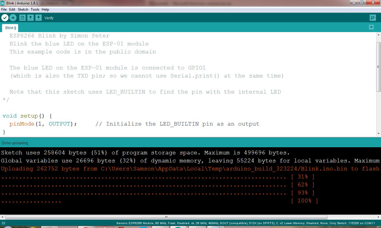
- Open test file. From File --> Examples --> ESP8266 --> Blink
- Upload the Blink program
- After upload is complete, the ESP8266-01's led should be blinking now.
- If you want to program the same module again, please power cycle it (unplug and plug in from the USB port) before program it.
Trouble shooting:
- Check your wiring
- Check your ESP8266's driver version is 2.5.0
- GND and GPIO0 has been shorted.
- Power cycle it
Proclamation:
- Above steps are learned from Electronic Guru's video, https://www.youtube.com/watch?v=P8Z-ZHwNeNI
Bonus:
Program ESP8266 ESP-01 with FT232RL FTDI USB to TTL Serial Converter Adapter

Proclamation:
Below procedure is inspired from https://iot-playground.com/blog/2-uncategorised/67-arduino-esp8266-ide
Program ESP8266 ESP-01 with FT232RL FTDI USB to TTL Serial Converter Adapter

Proclamation:
Below procedure is inspired from https://iot-playground.com/blog/2-uncategorised/67-arduino-esp8266-ide
Procedure:
1. Plug in above USB adapter
2. Check if your computer can find its COM port if yes, skip to step 4
3. Install driver manually from https://www.ftdichip.com/Drivers/VCP.htm or just run the EXE file from https://www.ftdichip.com/Drivers/CDM/CDM21228_Setup.zip.
4. Connect your adapter as shown in below diagram.
5. Setup your Arduino IDE for ESP8266 as shown in previous procedure.
6. Upload a test program, it should work now.
7. Before your try to upload another program, you need to reset it first (unplug and plug its power pin).
 |
| https://iot-playground.com/blog/2-uncategorised/67-arduino-esp8266-ide |
Other Code Example:
Below code is using ESP8266 ESP-01 with Adafruit's MQTT. LED on ESP-01 can be remotely turned on or off, and ESP-01 push a new value to io.adafruit. It is just for your reference only, and we will not discuss it in this project.
#include <ESP8266WiFi.h>
#include "Adafruit_MQTT.h"
#include "Adafruit_MQTT_Client.h"
/************************* WiFi Access Point *********************************/
#define WLAN_SSID "*******"
#define WLAN_PASS "*******"
/************************* Adafruit.io Setup *********************************/
#define AIO_SERVER "io.adafruit.com"
#define AIO_SERVERPORT 1883 // use 8883 for SSL
#define AIO_USERNAME "*******"
#define AIO_KEY "*******"
WiFiClient client;
Adafruit_MQTT_Client mqtt(&client, AIO_SERVER, AIO_SERVERPORT, AIO_USERNAME, AIO_KEY);
Adafruit_MQTT_Publish count = Adafruit_MQTT_Publish(&mqtt, AIO_USERNAME "/feeds/count");
Adafruit_MQTT_Subscribe onoffbutton = Adafruit_MQTT_Subscribe(&mqtt, AIO_USERNAME "/feeds/onoff");
void MQTT_connect();
void setup() {
Serial.begin(115200); delay(10);
// Connect to WiFi access point.
Serial.println(); Serial.println();
Serial.print("Connecting to ");
Serial.println(WLAN_SSID);
WiFi.begin(WLAN_SSID, WLAN_PASS);
while (WiFi.status() != WL_CONNECTED) {
delay(500);
Serial.print(".");
}
Serial.println();
pinMode(1, OUTPUT);
Serial.println("WiFi connected");
Serial.println("IP address: "); Serial.println(WiFi.localIP());
// Setup MQTT subscription for onoff feed.
mqtt.subscribe(&onoffbutton);
}
int count_value=0;
void loop() {
MQTT_connect();
Adafruit_MQTT_Subscribe *subscription;
while ((subscription = mqtt.readSubscription(5000))) {
if (subscription == &onoffbutton) {
Serial.print(F("Got: "));
Serial.println((char *)onoffbutton.lastread);
if(onoffbutton.lastread[1]==78){digitalWrite(1,HIGH);Serial.print("Light on");}
if(onoffbutton.lastread[1]==70){digitalWrite(1,LOW);Serial.print("Light off");}
}
}
count_value++ ;
// Now we can publish stuff!
Serial.print(F("\nSending pressure val ")); Serial.print(count_value);Serial.print("...");
if (! count.publish(count_value)) {Serial.println(F("Failed"));} else { Serial.println(F("OK!")); }
delay(1000);
}
// Function to connect and reconnect as necessary to the MQTT server.
// Should be called in the loop function and it will take care if connecting.
void MQTT_connect() {
int8_t ret;
// Stop if already connected.
if (mqtt.connected()) {
return;
}
Serial.print("Connecting to MQTT... ");
uint8_t retries = 3;
while ((ret = mqtt.connect()) != 0) { // connect will return 0 for connected
Serial.println(mqtt.connectErrorString(ret));
Serial.println("Retrying MQTT connection in 5 seconds...");
mqtt.disconnect();
delay(5000); // wait 5 seconds
retries--;
if (retries == 0) {
// basically die and wait for WDT to reset me
while (1);
}
}
Serial.println("MQTT Connected!");
}

No comments:
Post a Comment