Objective:
- Study the capability of the 5v RF transmitter ( FS1000A/XY-FST) and the 5v RF receiver (XY-MK-5V).
 |
| Top is ( FS1000A/XY-FST) and the bottom RF receiver (XY-MK-5V). |
 |
| Use Arduino to produce square wave, and as power supply to the Tx. A small capaceter add to data pin to reduce noise. |
 |
| There are three pin. From let to right are: Data pin, Vcc pin, and GND pin |
 |
| Rx circuit |
 |
| Pin from the left to the right are: Vcc, Data1, Data2, and GND. Note: Data 1 = Data 2 |
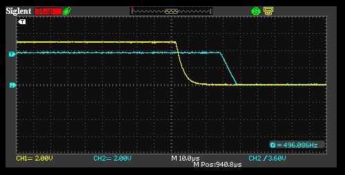 |
| 25us delay |
 |
| The lowest stable frequency is 2Hz. The receiver's voltage is ~4V. |
 |
| When frequency is too low, receiver cannot work normally |
 |
| The highest stable working frequency is 17KHz |
 |
| 1KHz 5% duty cycle work stably |
 |
| 1KHz 95% Duty cycle is not stable. But, 90% is stable. |
The operational frequency range:
- 2Hz to 17KHz with digital signal only
Power Consumption Range:
- Rx::30mW, =5Vx 6mA
- Tx: 35mW=5Vx7mA
Transmission range:
- 50ft distance in house and with 4 layer of dry wall has been tested
- Max distance is to be tested...
Summary:
- This is a simple and effective device digital RF Tx/Rx work. It can work with or without Arduino. If use it working with Arduino, you may not need library at all.
- Try to avoid sending and low frequency signal because it is unstable at low frequency. During idle time, try to send a based frequency as well. It does not work well with DC signal (H or L) signal.
No comments:
Post a Comment