Sunday, March 26, 2017

Study the capability of the RF transmitter ( FS1000A/XY-FST) and the receiver (XY-MK-5V).


Objective: 


Top is ( FS1000A/XY-FST) and the bottom RF receiver (XY-MK-5V).


Use Arduino to produce square wave, and as power supply to the Tx.  A small capaceter add to data pin to reduce noise.

There are three pin.  From let to right are: Data pin, Vcc pin, and GND pin

Rx circuit

Pin from the left to the right are: Vcc, Data1, Data2, and GND.  Note: Data 1 = Data 2

25us delay

The lowest stable frequency is 2Hz.  The receiver's voltage is ~4V.

When frequency is too low, receiver cannot work normally

The highest stable working frequency is 17KHz

1KHz 5% duty cycle work stably

1KHz 95% Duty cycle is not stable.  But, 90% is stable.

The operational frequency range:

  • 2Hz to 17KHz with digital signal only

Power Consumption Range:

  • Rx::30mW, =5Vx 6mA
  • Tx: 35mW=5Vx7mA

Transmission range:

  • 50ft distance in house and with 4 layer of dry wall has been tested
  • Max distance is to be tested...  


Summary:

  • This is a simple and effective device digital RF Tx/Rx work.  It can work with or without Arduino.  If use it working with Arduino, you may not need library at all.  
  • Try to avoid sending and low frequency signal because it is unstable at low frequency.  During idle time, try to send a based frequency as well.  It does not work well with DC signal (H or L) signal.

Wednesday, March 22, 2017

Arduino Automatic Garage Door Closer

Project Objective:

  • A device to monitor garage door's status.  If the door remains open for too long (for example, people forget to close it).  It will close the door by itself.  Some false positive and negative should be consider to software design to reduce the potential risk by using this device.


Feature: 

  1. Monitor the garage door is opened or closed
  2. If the door is open more then 540 second (9 min), it sounds slow reminder alarm.
  3. If the door remain in opened in 600 second (10 min), it will sound rapid door closing alarm 
  4. After the door switch is triggered, 
    1.  it will check the status of the door in 23 second.  
    2. 23 second is the door close and re-open cycle time if something/someone prevent the door from closing.
  5. If the door is still closed, it will back to normal monitor cycle. 
  6. If the door is still opened, it will attempt to close it again, and then stay in the infinity loop with error reminder (blanking LED and chipping) 
  7. Risk assessment, What if:
    1. FP: it will attempt to close the door twice.  It will end up just open and close the door.  
    2. FN: it will do nothing.
    3. The overall risk is low for using this device.
  8. It communicates to user with simple Morse code, such as "Hi" after initialized, or "D" after closing the garage door. 


Component List:

  • 1x Arduino Nano
  • 1x HC-SR04
  • 1x PC817 (or equivalent)
  • 1x A-1557 (or equivalent) 
  • 1x Red LED
  • 1x Green LED
  • 1x 5V Buzzer 
  • 1x 10K ohm resistor 
  • 1x 170 ohm LED resistor, (or any similar resistor)
  • 1x 440 ohm LED resistor, (or any similar resistor)
  • 1x 110 ohm PC817 resistor, (or any similar resistor)
  • 5V power supply
  • 1x power switch (for power supply)
  • 1x power switch or jumper (for mode selection)
  • 2x quick connector
  • Wires
  • Project enclosure box


Schematic:

It is a simple schematic (please excuse my chicken scratch...)

Breadboarding.  It is for example only, a bit difference from schematic. When you build it, please only reference to schematic

Assembly and integration.  Add a power switch.
Quick Connection for power and door switch
Installed on top of garage door.
It does NOT detecting door id open.


It detects the garage door is open (the red LED is ON)


Demo 1 (Normal operation.  User just forget to close the garage door.)


Demo 2 (None standard operation.  For example, someone or some thing prevent the door from closing)


Arduino Code:

/* Automatic Garage Door Closer Project
 *
 * Author: Samson Yang
 * Date: 3/20/2017
 *
 * Feature:
 *  1. Monitor the garage door is opened or closed
 *  2. If the door is open more then 540 second (9min), it sounds slow reminder alarm.
 *  3. If the door remain in opened in 600 second (10 min), it will sound rapid door closing alarm
 *  4. After the door switch is trigered,
 *    a. it will check the status of the door in 23 second.
 *    b. 23 second is the door close and re-open cycle time if something/someone prevent the door from closing.
 *  5. If the door is still closed, it will back to normal monitor cycle.
 *  6. If the door is still opened, it will attemp to close it again, and then stay in the inifinity loop with error reminder (blanking LED and chipping)
 *  7. Risk assesment, What if:
 *    a. FP: it will attemp to close the door twice.  It will end up just open and close the door.
 *    b. FN: it will do nothing.
 *    c. The overall risk is low for using this device.
 *  
 *  Note:
 *  * FP(false positive, dooe is closed, but sensor say it is opened).
 *  * FN(false negative, door is opened, but sensor say it is closed).
 *
 *  Pin Arrangement:
 *  D2 --> Garage door switch
 *  D4 --> Door status red LED
 *  D5 --> Test mode selection (with pull up)
 *  D7 --> US Trigger
 *  D8 --> US Echo
 *  D9 --> Buzzer
 *  
 *  
*/
#include <TimeLib.h>
bool buzer = 1;
int Pre_closing_alarm_time=540;   //after 9 minutes sound reminder
int Closing_door_time=600;        //after 10 minutes close door
int Closed_Door_Threshold=600;
int Time_check_door_is_closed=23000;  //Wait 23 sec, if door cannot be closed, it can be detected after 23 seconds.
long int count=0;

// the setup function runs once when you press reset or power the board
void setup() {
  Serial.begin(9600);
  pinMode(2, OUTPUT);   //Door Control switch
  pinMode(4, OUTPUT);   //Door status indicator
  pinMode(7, OUTPUT);   //Triger pin
  pinMode(9, OUTPUT);  //Alarm pin

  pinMode(8, INPUT);    //Counting pin
  pinMode(5, INPUT);    //Test pin, 1: testing, 0:Normal

  digitalWrite(2, LOW);
  digitalWrite(4, LOW);
  digitalWrite(7, LOW);
  digitalWrite(9, LOW);


  //Test mode when pin 5 is high
  if(digitalRead(5)){
    Pre_closing_alarm_time=3;
    Closing_door_time=7;
    Time_check_door_is_closed=10000;
  }
  say_hi();
}

int door_open_time=0;
void loop() {
  int time_gap=0;
  //count=0;

  bool door_status = check_door();

  //Check how much time the door has been opened
  time_gap=now()-door_open_time;

  //Door is opened
  if (door_status) {
    digitalWrite(4, HIGH); //Turn on door status indicator LED
    if (time_gap>Pre_closing_alarm_time){
      digitalWrite(9, buzer);
      buzer=!buzer;
      }
    }
 
  else {
    //Door is closed
    digitalWrite(4, LOW); //Turn off door status indicator LED
    door_open_time=now();
    digitalWrite(9, LOW); //Turn off buzer
  }

  //Check is it time to close the door
  if (time_gap>Closing_door_time){
    close_door();
    door_open_time=now();
  }

  //Send message out
  Serial.print("");Serial.print("  ");
  Serial.print(now());Serial.print("  ");Serial.println(door_open_time);

  //Max frequency is 10Hz, or use 100 or higher value
  delay(500);                    
}

void close_door(){
  int i;
  buzer = 1;
  for (i = 1;i<50;i++){
    digitalWrite(9, buzer);
    buzer=!buzer;
    delay(50);
  }
  digitalWrite(9, LOW);//Turn off buzer

  //Close garage door
  digitalWrite(2, HIGH);
  delay(1000);
  digitalWrite(2, LOW);

  delay(Time_check_door_is_closed);
  if (!check_door()) say_done();
  else {
    //Something wrong, and show slow blanking door status LED.
    //Try close and the door 2nd times  
    //It should mitigate FP (false positive).  Its means door is closed, but sensor think it is opened issue.
    //If there is FP, the second dooe closing activity, will close the door when the first FP open the door.
    buzer = 1;
    for (i = 1;i<100;i++){
      digitalWrite(9, buzer);
      buzer=!buzer;
      delay(100);
    }
    digitalWrite(9, LOW);//Turn off buzer
 
    //Close garage door
    digitalWrite(2, HIGH);
    delay(1000);
    digitalWrite(2, LOW);

    //Infinity loop and show blanking door status LED.
    while (1){
      digitalWrite(4, HIGH);
      delay(200);S();
      digitalWrite(4, LOW);
      delay(3000);
   
    }  
  }
}

bool check_door(){
  //if Closed return 0
  //if Opened return 1
  long int count_in=0;

  //Triger the signal
  digitalWrite(7, HIGH);
  digitalWrite(7, LOW);
 
  //Wait ultra sound echo
  while (!digitalRead(8));

  //Measure the distance
  while (digitalRead(8)){count_in++;}

  if (count_in<Closed_Door_Threshold)
    {return 1;}
  else
    {return 0;}
}

void say_done(){
  //Say mose code D (it means done)
  L();S();S();
}

void say_hi(){
  S();S();S();S();_();S();S();
}

void L(){
  digitalWrite(9, HIGH);
  delay(300);
  digitalWrite(9, LOW);
  delay(50);
}

void S(){
  digitalWrite(9, HIGH);
  delay(100);
  digitalWrite(9, LOW);
  delay(50);
}

void _(){
  digitalWrite(9, LOW);
  delay(300);
}

Saturday, March 11, 2017

Arduino TVOut Project

Objective:

    Experience with TVOut library with Arduino.


Software:

  • Download library from https://github.com/Avamander/arduino-tvout/
  • Note: For some reason, I cannot use the library as is.  During compiling, it pop up below error message.  I stuck in this step for weeks.


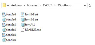
  • After I copy all files except README.md from under TVoutfronts folder, and paste them to its upper level folder TVOUT.  I can compile this Arduino code now.  :) If anyone know why this is happening, please let me know.  Thanks.


Copy file from above folder 


Paste file to above folder location


Reference website:


Hardware setup:

Arduino Uno Pin 9: Sync
Arduino Uno Pin 7: Video


Simple Hardware Setup


Arduino Code -1:

#include <TVout.h>
#include <fontALL.h>

TVout TV;
int sensorPin = A0;
int sensorValue = 0;

void setup()  {
  TV.begin(NTSC);  
  TV.select_font(font6x8);
}

void loop() {
  int x, y;

  TV.draw_line(0,0,0,95,1);
  TV.draw_line(0,0,127,0,1);
  TV.draw_line(0,95,127,95,1);
  TV.draw_line(127,0,127,95,1);

  for(y=0;y<TV.vres();y++){
    for(x=0;x<TV.hres();x++){
      TV.set_cursor(40,43);TV.print("(");TV.print(x);TV.print(", ");TV.print(y);TV.print(")  ");
      TV.set_pixel(x,y,2);
    }
  }
  TV.clear_screen(); 
}


Simple Demo

Arduino Code -2:


#include <TVout.h>
#include <fontALL.h>
#include "schematic.h"
#include "TVOlogo.h"

TVout TV;

int zOff = 150;
int xOff = 0;
int yOff = 0;
int cSize = 50;
int view_plane = 64;
float angle = PI/60;

float cube3d[8][3] = {
  {xOff - cSize,yOff + cSize,zOff - cSize},
  {xOff + cSize,yOff + cSize,zOff - cSize},
  {xOff - cSize,yOff - cSize,zOff - cSize},
  {xOff + cSize,yOff - cSize,zOff - cSize},
  {xOff - cSize,yOff + cSize,zOff + cSize},
  {xOff + cSize,yOff + cSize,zOff + cSize},
  {xOff - cSize,yOff - cSize,zOff + cSize},
  {xOff + cSize,yOff - cSize,zOff + cSize}
};
unsigned char cube2d[8][2];


void setup() {
  TV.begin(NTSC,120,96);
  TV.select_font(font6x8);
  intro();
  TV.println("I am the TVout\nlibrary running on a freeduino\n");
  TV.delay(2500);
  TV.println("I generate a PAL\nor NTSC composite  video using\ninterrupts\n");
  TV.delay(2500);
  TV.println("My schematic:");
  TV.delay(1500);
  TV.bitmap(0,0,schematic);
  TV.delay(10000);
  TV.clear_screen();
  TV.println("Lets see what\nwhat I can do");
  TV.delay(2000);
  
  //fonts
  TV.clear_screen();
  TV.println(0,0,"Multiple fonts:");
  TV.select_font(font4x6);
  TV.println("4x6 font FONT");
  TV.select_font(font6x8);
  TV.println("6x8 font FONT");
  TV.select_font(font8x8);
  TV.println("8x8 font FONT");
  TV.select_font(font6x8);
  TV.delay(2000);
  
  TV.clear_screen();
  TV.print(9,44,"Draw Basic Shapes");
  TV.delay(2000);
  
  //circles
  TV.clear_screen();
  TV.draw_circle(TV.hres()/2,TV.vres()/2,TV.vres()/3,WHITE);
  TV.delay(500);
  TV.draw_circle(TV.hres()/2,TV.vres()/2,TV.vres()/2,WHITE,INVERT);
  TV.delay(2000);
  
  //rectangles and lines
  TV.clear_screen();
  TV.draw_rect(20,20,80,56,WHITE);
  TV.delay(500);
  TV.draw_rect(10,10,100,76,WHITE,INVERT);
  TV.delay(500);
  TV.draw_line(60,20,60,76,INVERT);
  TV.draw_line(20,48,100,48,INVERT);
  TV.delay(500);
  TV.draw_line(10,10,110,86,INVERT);
  TV.draw_line(10,86,110,10,INVERT);
  TV.delay(2000);
  
  //random cube forever.
  TV.clear_screen();
  TV.print(16,40,"Random Cube");
  TV.print(28,48,"Rotation");
  TV.delay(2000);
  
  randomSeed(analogRead(0));
}

void loop() {
  int rsteps = random(10,60);
  switch(random(6)) {
    case 0:
      for (int i = 0; i < rsteps; i++) {
        zrotate(angle);
        printcube();
      }
      break;
    case 1:
      for (int i = 0; i < rsteps; i++) {
        zrotate(2*PI - angle);
        printcube();
      }
      break;
    case 2:
      for (int i = 0; i < rsteps; i++) {
        xrotate(angle);
        printcube();
      }
      break;
    case 3:
      for (int i = 0; i < rsteps; i++) {
        xrotate(2*PI - angle);
        printcube();
      }
      break;
    case 4:
      for (int i = 0; i < rsteps; i++) {
        yrotate(angle);
        printcube();
      }
      break;
    case 5:
      for (int i = 0; i < rsteps; i++) {
        yrotate(2*PI - angle);
        printcube();
      }
      break;
  }
}

void intro() {
unsigned char w,l,wb;
  int index;
  w = pgm_read_byte(TVOlogo);
  l = pgm_read_byte(TVOlogo+1);
  if (w&7)
    wb = w/8 + 1;
  else
    wb = w/8;
  index = wb*(l-1) + 2;
  for ( unsigned char i = 1; i < l; i++ ) {
    TV.bitmap((TV.hres() - w)/2,0,TVOlogo,index,w,i);
    index-= wb;
    TV.delay(50);
  }
  for (unsigned char i = 0; i < (TV.vres() - l)/2; i++) {
    TV.bitmap((TV.hres() - w)/2,i,TVOlogo);
    TV.delay(50);
  }
  TV.delay(3000);
  TV.clear_screen();
}

void printcube() {
  //calculate 2d points
  for(byte i = 0; i < 8; i++) {
    cube2d[i][0] = (unsigned char)((cube3d[i][0] * view_plane / cube3d[i][2]) + (TV.hres()/2));
    cube2d[i][1] = (unsigned char)((cube3d[i][1] * view_plane / cube3d[i][2]) + (TV.vres()/2));
  }
  TV.delay_frame(1);
  TV.clear_screen();
  draw_cube();
}

void zrotate(float q) {
  float tx,ty,temp;
  for(byte i = 0; i < 8; i++) {
    tx = cube3d[i][0] - xOff;
    ty = cube3d[i][1] - yOff;
    temp = tx * cos(q) - ty * sin(q);
    ty = tx * sin(q) + ty * cos(q);
    tx = temp;
    cube3d[i][0] = tx + xOff;
    cube3d[i][1] = ty + yOff;
  }
}

void yrotate(float q) {
  float tx,tz,temp;
  for(byte i = 0; i < 8; i++) {
    tx = cube3d[i][0] - xOff;
    tz = cube3d[i][2] - zOff;
    temp = tz * cos(q) - tx * sin(q);
    tx = tz * sin(q) + tx * cos(q);
    tz = temp;
    cube3d[i][0] = tx + xOff;
    cube3d[i][2] = tz + zOff;
  }
}

void xrotate(float q) {
  float ty,tz,temp;
  for(byte i = 0; i < 8; i++) {
    ty = cube3d[i][1] - yOff;
    tz = cube3d[i][2] - zOff;
    temp = ty * cos(q) - tz * sin(q);
    tz = ty * sin(q) + tz * cos(q);
    ty = temp;
    cube3d[i][1] = ty + yOff;
    cube3d[i][2] = tz + zOff;
  }
}

void draw_cube() {
  TV.draw_line(cube2d[0][0],cube2d[0][1],cube2d[1][0],cube2d[1][1],WHITE);
  TV.draw_line(cube2d[0][0],cube2d[0][1],cube2d[2][0],cube2d[2][1],WHITE);
  TV.draw_line(cube2d[0][0],cube2d[0][1],cube2d[4][0],cube2d[4][1],WHITE);
  TV.draw_line(cube2d[1][0],cube2d[1][1],cube2d[5][0],cube2d[5][1],WHITE);
  TV.draw_line(cube2d[1][0],cube2d[1][1],cube2d[3][0],cube2d[3][1],WHITE);
  TV.draw_line(cube2d[2][0],cube2d[2][1],cube2d[6][0],cube2d[6][1],WHITE);
  TV.draw_line(cube2d[2][0],cube2d[2][1],cube2d[3][0],cube2d[3][1],WHITE);
  TV.draw_line(cube2d[4][0],cube2d[4][1],cube2d[6][0],cube2d[6][1],WHITE);
  TV.draw_line(cube2d[4][0],cube2d[4][1],cube2d[5][0],cube2d[5][1],WHITE);
  TV.draw_line(cube2d[7][0],cube2d[7][1],cube2d[6][0],cube2d[6][1],WHITE);
  TV.draw_line(cube2d[7][0],cube2d[7][1],cube2d[3][0],cube2d[3][1],WHITE);
  TV.draw_line(cube2d[7][0],cube2d[7][1],cube2d[5][0],cube2d[5][1],WHITE);
}


Friday, February 10, 2017

AT24C256 EEPROM with Arduino

AT24C256 EEPROM CHIP Demo
2/10/2017

Project Scope:
Test EEPROM with Arduino with basic write and read function.

Circuit connection:
Arduino ----  24C256
A5 ----- 6
 A4 ----- 5
GND ----- 4, 7
      VCC ----- 1, 2 & 8


Circuit Layout

Test Result


Arduino Code

//Modified from http://playground.arduino.cc/Code/I2CEEPROM
//Note: Device address
//if A1-->GND, A0-->GND -->0x50
//if A1-->GND, A0-->Vcc -->0x51
//if A1-->Vcc, A0-->GND -->0x52
//if A1-->Vcc, A0-->Vcc -->0x53

#include<Wire.h>

void setup() {
  Serial.begin(9600);
  Wire.begin();
  char somedata[]="This is only a test.";
 
  //Write a page
  i2c_eeprom_write_page(0x53, 0, (byte*)somedata, sizeof(somedata));delay(10);

  //Wirte number 125 to address 100
  i2c_eeprom_write_byte(0x53, 100, 123);delay(10);
  Serial.println("Data written.");
}


void loop() {
  int addr=0;

  //Read page of data
  byte b=i2c_eeprom_read_byte(0x53,addr);
  while (b!=0){
    Serial.print((char)b);
    addr++;
    b=i2c_eeprom_read_byte(0x53,addr);
  }
  Serial.println("  ");

  //Read a byte
  b=i2c_eeprom_read_byte(0x53,100);
  Serial.println((int)b);

  delay(10000);
}

void i2c_eeprom_write_byte(int device_address, unsigned int ee_address, byte data){
  Wire.beginTransmission(device_address);
  Wire.write((int)(ee_address >> 8)); //MSB
  Wire.write((int)(ee_address & 0xFF)); //LSB
  Wire.write(data);
  Wire.endTransmission();
}

//Cannot longer then 30 byte.
void i2c_eeprom_write_page(int device_address, unsigned int ee_address_page, byte* data,byte lengths){
  Wire.beginTransmission(device_address);
  Wire.write((int)(ee_address_page >> 8)); //MSB
  Wire.write((int)(ee_address_page & 0xFF)); //LSB
  byte c;
  for(c=0;c<lengths;c++)Wire.write(data[c]);
  Wire.endTransmission();
}

byte i2c_eeprom_read_byte(int device_address, unsigned int ee_address){
  byte rdata=0xFF;
  Wire.beginTransmission(device_address);
  Wire.write((int)(ee_address >> 8)); //MSB
  Wire.write((int)(ee_address & 0xFF)); //LSB
  Wire.endTransmission();
  Wire.requestFrom(device_address,1);
  while(!Wire.available()){ }
  rdata=Wire.read();
  return rdata;
}

Thursday, February 9, 2017

AD9850 Clock Generator with Arduino

AD9850 Clock Generator 
With Arduino
5/7/2016


Project Scope:

Create an adjustable frequency generator.  One encoder for frequency step adjustment and another one is for frequency adjustment.  Frequency range:  See AD9850 for detail.


Material:

1x Arduino Uno
2x AD9850
3x LCD Display
2x Encoder


Circuit Connection:

Arduino to AD9850
 Vcc ------- Vcc
      8 ------- W_CK
      9 ------- FU_UD
     10 ------- DATA
     11 ------- RESET
GND ------- GND

Arduino to LCD
   A5  -------  SCL
   A4  -------  SDA
  Vcc  -------  Vcc
GND  -------  GND

Arduino to Encoder #1
       4  -------  CLK
       5  -------  DT
               x     SW
   Vcc  ------- Vcc
GND  ------- GND

Arduino to Encoder #2
       2  -------  CLK
       3  -------  DT
               x     SW
   Vcc  ------- Vcc
GND  ------- GND


Pictures:

LCD Module

AD9850 Module (Front)

AD9850 Module (Back)

Encoder Module


Integrated Module -1

Integrated Module -2

Integrated Module -3

Output from ZOUT1

Adjustment Demo


/*
 * Original AD9851 DDS sketch by Andrew Smallbone at www.rocketnumbernine.com
 * Modified by Samson with frequency adjustment feature
 * 9850 datasheet at http://www.analog.com/static/imported-files/data_sheets/AD9850.pdf
 *
 * LCD Display, use the following libery
 * https://arduino-info.wikispaces.com/LCD-Blue-I2C
 * Choose NewliquidCrystal_1.3.4.zip
 */

#include <Wire.h>
#include <LiquidCrystal_I2C.h>

 #define W_CLK 8       // Pin 8 - connect to AD9850 module word load clock pin (CLK)
 #define FQ_UD 9       // Pin 9 - connect to freq update pin (FQ)
 #define DATA 10       // Pin 10 - connect to serial data load pin (DATA)
 #define RESET 11      // Pin 11 - connect to reset pin (RST).
 #define R11 2
 #define R12 3
 #define R21 4
 #define R22 5

 #define pulseHigh(pin) {digitalWrite(pin, HIGH); digitalWrite(pin, LOW); }
 #define BACKLIGHT_PIN     13

LiquidCrystal_I2C lcd(0x27,2,1,0,4,5,6,7,3,POSITIVE);  // Set the LCD I2C address

 // transfers a byte, a bit at a time, LSB first to the 9850 via serial DATA line
void tfr_byte(byte data)
{
  for (int i=0; i<8; i++, data>>=1) {
    digitalWrite(DATA, data & 0x01);
    pulseHigh(W_CLK);   //after each bit sent, CLK is pulsed high
  }
}

 // frequency calc from datasheet page 8 = <sys clock> * <frequency tuning word>/2^32
void sendFrequency(double frequency) {
  int32_t freq = frequency * 4294967295/125000000;  // note 125 MHz clock on 9850
  for (int b=0; b<4; b++, freq>>=8) {
    tfr_byte(freq & 0xFF);
  }
  tfr_byte(0x000);   // Final control byte, all 0 for 9850 chip
  pulseHigh(FQ_UD);  // Done!  Should see output
}

void setup() {
 // configure arduino data pins for output
  Serial.begin(9600);
  pinMode(R11, INPUT);
  pinMode(R12, INPUT);
  pinMode(R21, INPUT);
  pinMode(R22, INPUT);

  pinMode(FQ_UD, OUTPUT);
  pinMode(W_CLK, OUTPUT);
  pinMode(DATA, OUTPUT);
  pinMode(RESET, OUTPUT);

  pulseHigh(RESET);
  pulseHigh(W_CLK);
  pulseHigh(FQ_UD);  // this pulse enables serial mode - Datasheet page 12 figure 10

  //Serial.begin(9600);
    pinMode ( BACKLIGHT_PIN, OUTPUT );
  digitalWrite ( BACKLIGHT_PIN, HIGH );

  lcd.begin(16,2);               // initialize the lcd
  cleanLCD(0);lcd.setCursor ( 0, 0 ); lcd.print ("Signal Generator");
  cleanLCD(1);lcd.setCursor ( 0, 1 ); lcd.print ("V1.0 5/7/2016 SY");
  delay (5000);
  cleanLCD(1);lcd.setCursor ( 0, 1 ); lcd.print ("Step: 100 KHz");
}
double set_freq=1.1e6;
double set_incem=100000;
int r11pv=0;
int r12pv=0;
int r21pv=0;
int r22pv=0;

void cleanLCD(int i){
  lcd.setCursor ( 0, i );
  lcd.print ("                      ");
}
void loop() {
  int r11v = digitalRead(R11);
  int r12v = digitalRead(R12);
  int r21v = digitalRead(R21);
  int r22v = digitalRead(R22);

  int k=1;
  if (r11v!=r11pv){
    if(r11v==1)k=1;else k=-1;
    if (r12v==0)set_freq=set_freq+set_incem*k;
    if (r12v==1)set_freq=set_freq-set_incem*k;
    if (set_freq<0)set_freq=0;
    if (set_freq>1e8)set_freq=1e8;
    sendFrequency(set_freq);  // freq
    Serial.print("Frequency: ");
    if ((set_freq<1000)){Serial.print(set_freq,0);Serial.println("Hz.");}
    if ((set_freq>=1000)*(set_freq<1000000)){Serial.print((set_freq/1000),3);Serial.println("KHz.");}
    if ((set_freq>=1000000)){Serial.print((set_freq/1000000),3);Serial.println("MHz.");}
 
   if ((set_freq<1000)){cleanLCD(0);lcd.setCursor ( 0, 0 ); lcd.print ("Set: ");lcd.print (set_freq,0);lcd.print (" Hz");}
   if ((set_freq>=1000)*(set_freq<1000000)){cleanLCD(0);lcd.setCursor ( 0, 0 ); lcd.print ("Set: ");lcd.print (set_freq/1000,3);lcd.print (" KHz");}
   if ((set_freq>=1000000)){cleanLCD(0);lcd.setCursor ( 0, 0 ); lcd.print ("Set: ");lcd.print (set_freq/1000000,3);lcd.print (" MHz");}


  }

  if (r21v!=r21pv){
    if ((r22v==0)*(r21v==1))set_incem=double(set_incem*10);
    if ((r22v==0)*(r21v==0))set_incem=double(set_incem/10);
    if ((r22v==1)*(r21v==1))set_incem=double(set_incem/10);
    if ((r22v==1)*(r21v==0))set_incem=double(set_incem*10);
    if (set_incem<1)set_incem=1;
    if (set_incem>1e7)set_incem=1e7;
    //sendFrequency(set_freq);  // freq
    //Serial.print("Set increatment:");Serial.println(set_incem,0);
    Serial.print("Frequency increament: ");
    if ((set_incem<1000)){Serial.print(set_incem,0);Serial.println("Hz.");}
    if ((set_incem>=1000)*(set_incem<1000000)){Serial.print((set_incem/1000),0);Serial.println("KHz.");}
    if ((set_incem>=1000000)){Serial.print((set_incem/1000000),0);Serial.println("MHz.");}

    Serial.print("Frequency increament: ");
    if ((set_incem<1000)){cleanLCD(1);lcd.setCursor ( 0, 1 ); lcd.print ("Step: ");lcd.print (set_incem,0);lcd.print (" Hz");}
    if ((set_incem>=1000)*(set_incem<1000000)){cleanLCD(1);lcd.setCursor ( 0, 1 ); lcd.print ("Step: ");lcd.print (set_incem/1000,0);lcd.print (" KHz");}
    if ((set_incem>=1000000)){cleanLCD(1);lcd.setCursor ( 0, 1 ); lcd.print ("Step: ");lcd.print (set_incem/1000000,0);lcd.print (" MHz");}
 
    }


  r11pv=r11v;r12pv=r12v;
  r21pv=r21v;r22pv=r22v;
  //delay(50);
}